Welcome to Wheel Tech Talk. This page will help to provide information about wheels. If there is anything that you wish to suggest we add to this page, please feel free to contact us [email protected] .
Cast Alloy Wheel
The most common and cost effective manufacturing method of an alloy wheel is casting. Cast wheels are generally made from A356 aluminium alloy and can be made by two methods, gravity or pressure. The aluminium alloy for the wheel is heated up into a molten liquid state ready to be pushed or poured. Gravity casting is the most common casting process which involves just pouring the alloy into the mold. Pressure casting is better than gravity casting as it results in a higher quality wheel. This is because the pressure forces the aluminium into shape, making it more dense and reducing the risk of inconsistencies. However, this is more complicated and expensive over gravity casting. The downside to casting is that, as the liquid alloy cools in the mold, there is a chance for greater porosity or inconsistencies in the metal as mentioned. The pressure method does help to reduce this over the gravity method. To reduce the chance of inconsistencies leading to a wheel cracking from weakness, more material needs to be used in casting compared to the other manufacturing methods. While this does result in a heavier wheel compared to flow formed or forged, it is still lighter than a steel wheel. With most applications for cast wheels not being that of high performance and low weight, they are the perfect low cost way to enhance the visual appeal of a vehicle. Cast wheels are safe and great choice for regular, everyday drivers. They are not ideal for racing or off-roading, but can be used in these areas. For serious performance, flow formed or forged wheels are a better option, but come with a higher price.
Flow Formed Alloy Wheel
There are many names used to describe this type of manufactured wheel. Some of these names used are rotary forged, rotary formed, spun forged, semi-forged and flow forged. While there are some different techniques used, they are all essentially the exact same process. This is a relatively new method of alloy wheel manufacturing that is a hybrid between a cast wheel and a forged wheel. With the barrel of the wheel shaped under high pressure and high heat in the same way as many forged wheels, the barrel and only the barrel is in technical terms… forged. However, a flow form wheel is not to be confused with a forged wheel. The process under which a forged wheel is made, along with the alloy used, is different. Flow formed wheels are a step up in cost, strength and weight saving compared to cast wheels. The process starts the same as a cast wheel and out of A356 aluminium alloy, but then is finished a different way to get its final shape. Once the initial shape of the wheel is created from usually a low pressure casting method (as this is the optimum method for a high quality cast wheel), the barrel is then formed with high heat and high pressure with rollers over a mandrel to the size of the specific barrel width to be formed. This process better aligns the alloy grain structure of the barrel, making it lighter and stronger over a cast barrel. Flow formed wheels are anywhere between 15% to 25% lighter than a cast equivalent and of course stronger. Flow formed wheels are a great option for those who want something lighter and more durable than a cast wheel, but cost less than a forged wheel. On the track, for example, less weight leads to less rotating mass, a benefit for both greater acceleration and breaking efficiency. On the road, lighter wheels can offer a better ride as they reduce unsprung weight allowing the suspension to work more efficiently. Also the benefits of a flow form wheel on the road is that it’s chances of cracking from going through a bad pot hole are greatly reduced. Flow form wheel barrels in this situation are more prone to bend than crack.
Forged Alloy Wheel
Forged alloy wheels are at the top of the wheel performance list because they are the strongest wheels on the market. Forged wheels are made from a solid block of 6061 (also 7075 for even greater strength and weight savings but at an even higher cost) aluminium alloy that is heated and pressed using a lot of pressure to force the alloy into shape. This process causes it to become uniform in grain structure, giving it the strength it needs and removes the possibility of being porous and other structural issues. The 6061 alloy is also tempered to increase it’s strength. The level of temper is displayed as -T6 (6061-T6). The result is a very strong and consistent alloy which allows a lot of material to be machined off while still maintaining the strength required to have a strong wheel. Compared to cast and flow formed wheels, forged wheels can have significantly less material while maintaining the same or more strength, which is what allows them to be so light. Unfortunately, the forging process is complex and expensive, which is why these wheels cost so much. Forged wheels are often available in monoblock and multi-piece configurations.
Diameter
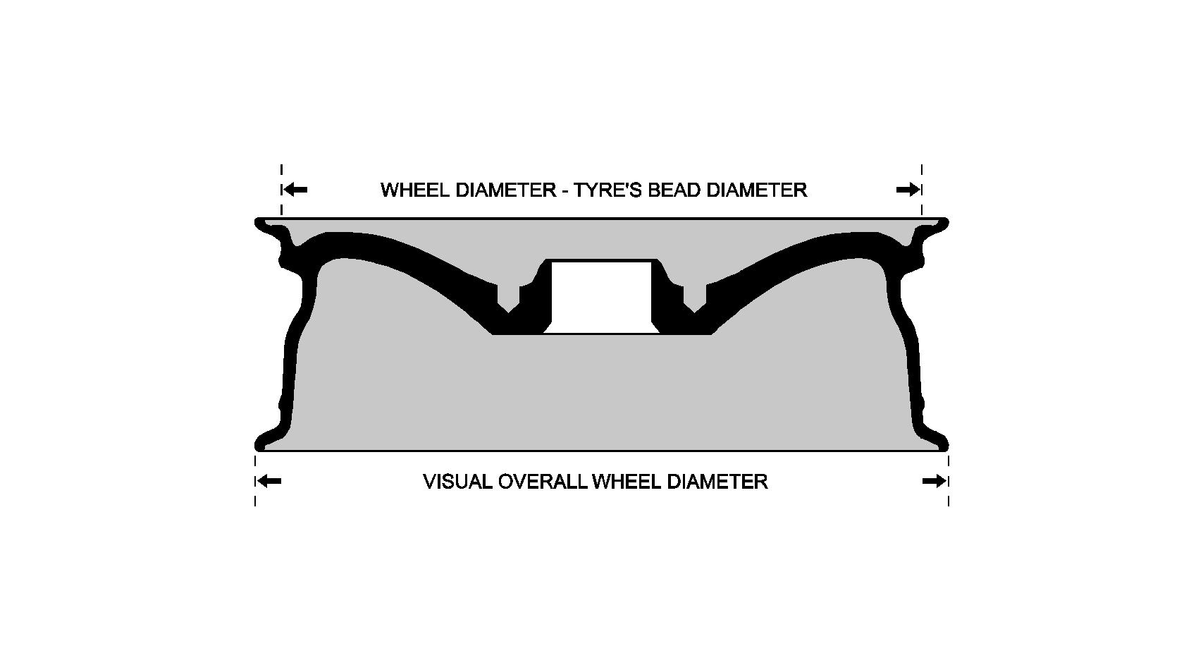
This measurement used for a wheel diameter is the diameter of which the tyre bead will sit on the barrel of the wheel. This measurement is not the actual visual diameter of the wheel. If you were to measure the diameter of a wheel stated to be 18″, you would find it would measure around 19″ or more edge to edge. This extra part is the flange of which creates part of the the tyre’s bead seat. If you were to measure the inside of a tyre for the same size wheel mentioned, it would be 18″.

Width
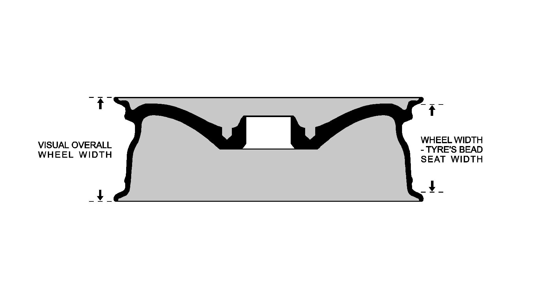
The width of a wheel is a number given in inches (the same as diameter) and usually followed by the letter J when it is displayed on the wheel itself. An example of this would be 18 x 9J. This number is the distance between the inside faces of the wheel barrel’s front and rear flanges. The inside faces of the barrel’s flanges are for the tyre’s bead to sit against and form an air tight seal.

Bolt Pattern
The bolt pattern is the number and position of the fixing holes in the wheel. These need to match the studs or bolt holes on your vehicle’s hub. This pattern is commonly referred to as the pitch circle diameter (P.C.D.). This number will be the amount of holes evenly spaced around the diameter that runs through their centres.
Offset
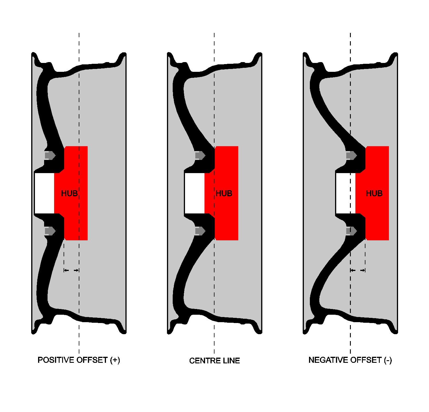
The term offset (also abbreviated ET) is from the Deutsche word “einpresstiefe”. It is the distance between the true centre line of the wheel across it’s width to the vehicle hub. The measurement is given in millimeters (metric) and can take both positive and negative values. A positive offset, such as ET+30, means there is a space of 30mm between the mounting face of the wheel and the wheel’s centre line. An offset of ET0, would indicated that the wheel’s mounting face is inline with the center line of the wheel. A negative offset ET-30 would be the mounting face 30mm towards the back of the wheel from the centre line. The higher (positive) the offset of a wheel, the more the wheel will sit inside the wheel arch. The lower (negative) the offset, the more the wheel will sit towards the outside of the wheel arch.
The offset can be the most tricky part to work out, as it will need to be changed if you increase/decrease your wheel width but want your wheel’s face to sit in the same position. When going for the same width as the wheel coming off of the vehicle, in most cases a wheel within +/-10mm of the original will fit without any clearance issues. Some vehicles have a lot of clearance room for the wheel to sit further into the vehicle or further out, but when unsure, going with +/-10mm is safe.
So let’s say you have your O.E.M. (Original Equipment Manufacturer) wheel that the vehicle left the factory with and it is 18×8 ET+40. You should easily be able to fit a wheel that is 18×8 ET+30 (which would have the wheel sitting out from the vehicle by 10mm more) or 18×8 ET+50 (which would have the wheel sitting into the vehicle by 10mm more). Alternatively, if you were to replace the same example 18×8 ET+40 with a new wheel that is 18×8.5 ET+40, then the front side of the wheel would be out 6.35mm more than before and the rear side of the wheel would be in 6.35 more than before. If you wanted the front of the 18×8.5 to sit in pretty much the same position as the original 18×8 ET+40, then you would add 6mm onto 40 giving a new offset of ET+46 (to be exactly the same it would be adding 6.35mm, but offsets are done in 1mm increments).

Centre Bore
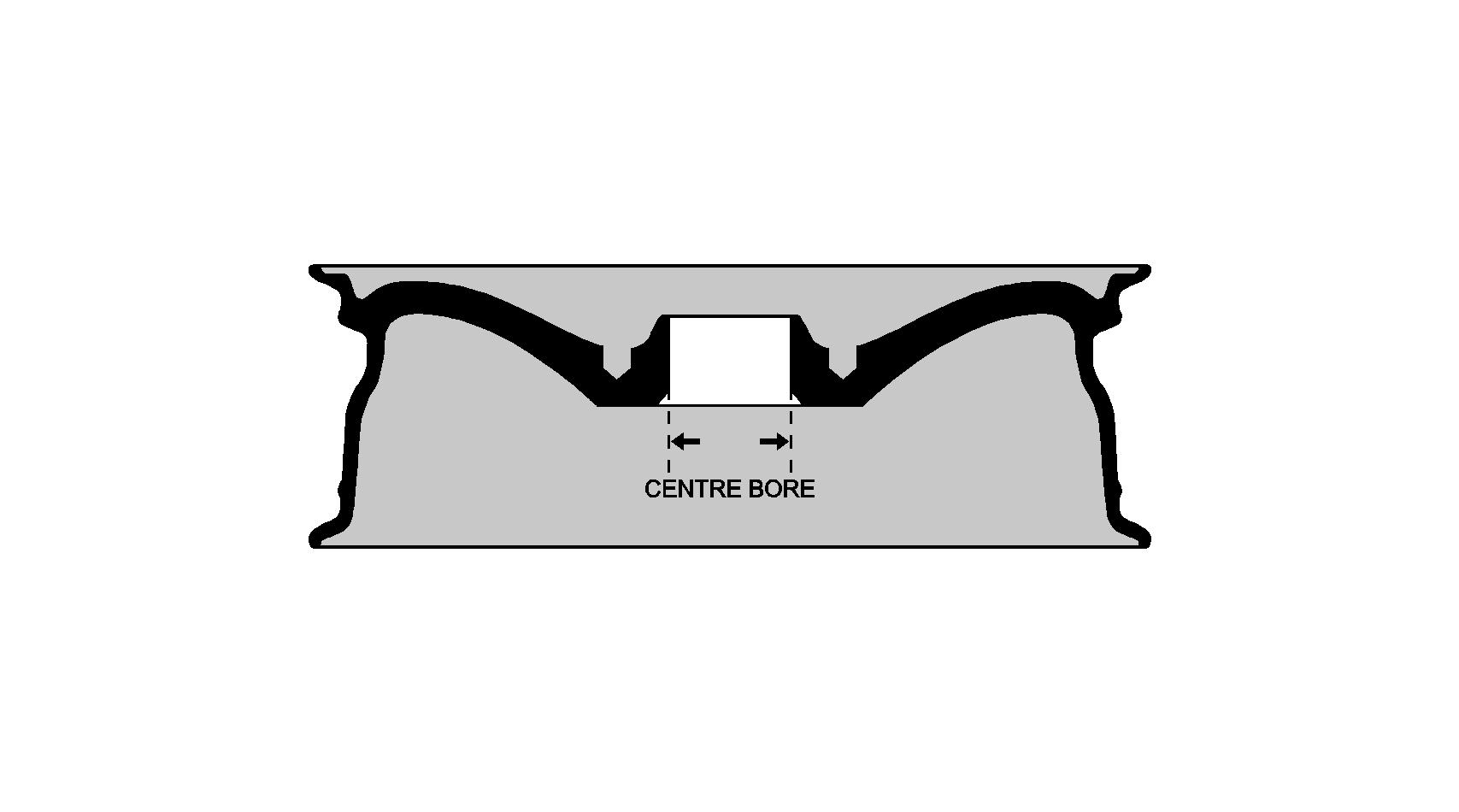
The centre bore is the diameter of the mounting face hole of the wheel and often given in millimetres. This should be the same size as the vehicle’s hub mounting. A wheel with a larger centre bore than the vehicle’s hub is perfectly fine as it can be corrected to the right size with the use of a spigot ring. Having a wheel with the correct centre bore, for the vehicle it is to be fitted to, will make sure the wheel is perfectly aligned to the vehicle’s hub and eliminate any wheel wobble. If a wheel has the correct bolt pattern P.C.D. of the vehicle’s hub mounting face, but the centre bore is smaller than the vehicle’s hub, then the wheel CANNOT be fitted.

Spigot Ring
A spigot ring is a simple insert that goes into a wheel’s centre bore if the centre bore is larger than the hub of the vehicle it is to be fitted to. Spigot rings are only used when the centre bore is larger than the vehicle’s hub. This will perfectly align the wheel centre bore to the vehicle hub eliminating any wheel wobble from an off centred wheel. A spigot ring will have it’s outside diameter to the same of the wheel’s centre bore and it’s inside diameter the same of the vehicle’s hub. So if you have a wheel that has a centre bore of 73.1 and the vehicle’s hub is 63.4, you would use a spigot ring that is 73.1 OD to 63.4 ID.
Load Rating
The load rating is the load of which the wheel has been rated to before it can fail. With most passenger cars this is not an issue to be considered to make a note of, but with heavy vehicles, commercial and now days very common electric vehicles, load rating should be taken into consideration. A quick guide to working out a minimum load rating of a wheel for your vehicle is to find out your vehicle’s gross vehicle weight (GVW) or permissible maximum weight. This is the maximum weight the vehicle manufacturers have built the vehicle to operate safely with fully loaded. It will be listed in the owner’s manual and is normally shown on a plate or sticker fitted to your vehicle. With not all vehicles running a 50/50 weight distribution across the front and rear axle and the majority running more 60/40, an easy way is to use the 60 and work with 60% of the GVW. So let’s say your vehicle’s unloaded weight, or kerb weight, is 1750kg but it has a rated GVW of 2,300kg. In this example, this vehicle can have upto 550kg of driver, passengers and/or cargo. So now we use the GVW of 2,300 and multiply it by 0.6 and end up with 1,380. So 1,380 is 60% of the GVW that is either over the front or rear axle. Now we divide 1,380 by 2, as you generally have 2 wheels per axle, and we have 690kg. So with that quick estimate working out, we would be looking for a wheel that has a load rating of 690kg or higher.

